

1. Detailed explanation of the standard size of imperial keyways
a. Core parameters
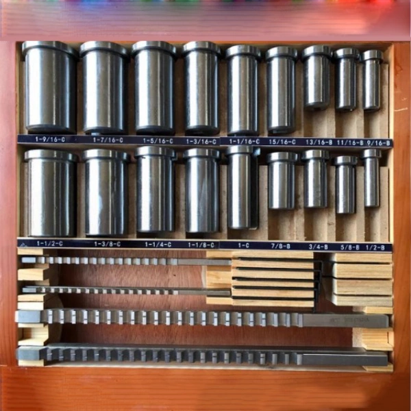
The imperial keyway size is based on the ANSI B17.1 standard, and the main parameters include:
– Width (W): Common sizes are 1/8″, 3/16″, 1/4″ (tolerance ± 0.002″).
– Depth (D): e.g. 1/4″ keyway depth of 0.125″ (shaft) / 0.093″ (hub) with tolerance reference ISO R773.
– Length (L): Calculated based on shaft diameter, typically 1.5 times the shaft diameter.
b. Differences from American standards
American keyways (ANSI B17.2) are the same width but with tighter tolerances, such as 1/4″ keyway tolerance of 0.000/-0.001″.
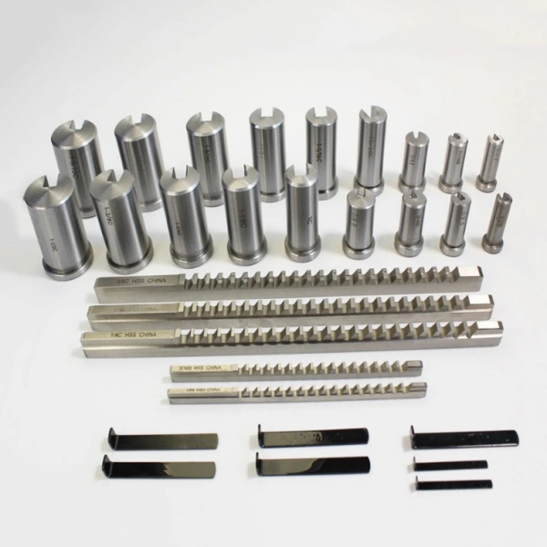
2. Comparison of imperial flat key specifications and parameters
a. Flat key size chart
Imperial flat keys (ASME B18.25.1) are divided into square keys and flat keys:
– Square key: height = width, e.g. 1/4″×1/4″.
– Rectangular Keys: 50%-75% of width in height, such as 1/4″×3/16″.
Key parameters:
– Material: Typically carbon steel (AISI 1045) or stainless steel (AISI 316).
– Fit tolerances: key height h9, keyway h9 (loose fit) or P9 (tight fit).
b. Flat key selection basis
– Shaft diameter ≤1″: Square keys are selected.
– Shaft diameter >1″: Priority rectangular keys are given to reduce stress concentrations.
3. Supplementary explanation of American standards
a. Conversion of American keyways to imperial keyways
1 inch = 25.4mm, but the width sequence of the US keyway is the same as the imperial system, only the tolerance is different (e.g. 3/16″ keyway US tolerance is ±0.0015″).
b. Application scenarios
– Imperial: General machinery (e.g., agricultural machinery, drive shaft).
– Made in the United States: high-precision equipment (e.g. aero engines).
Data sources:
– ANSI B17.1-1967 (R2020) “Imperial Keyway Standard”
– ASME B18.25.1M-2018 “Flat Key Dimensions and Tolerances”